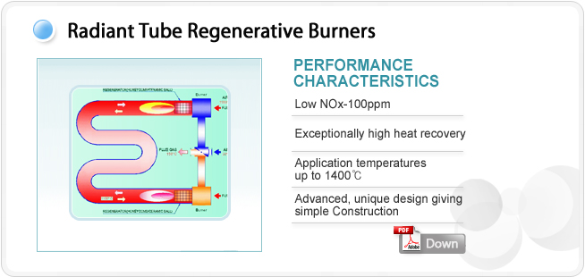
RADIANT TUBE REGENERATIVE SYSTEM
PRINCIPLE OF OPERATION
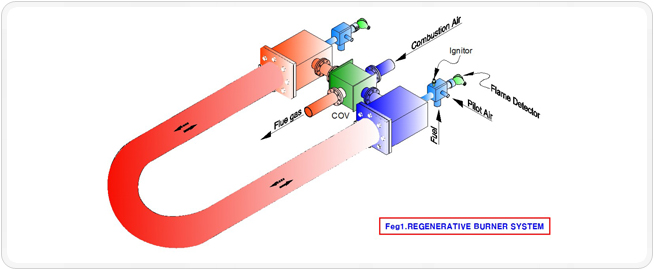
The burners are operated in two modes, an exhaust anda firing mode.
In the exhaust mode the regenerator bed recovers energy from the flue gases and in the firing mode the stored
energy is transferred to the combustionair.
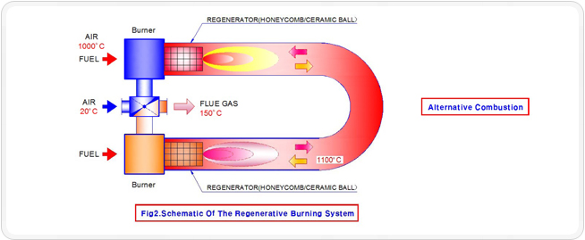
The combustion air inlet to the burner/regenerator thus becomes the exhaust port when the burner is in the exhaust mode.
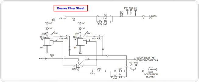
A simple schematic is given in figure 2.
In its simplest from the cycle controller must signal the valves in theair and fuel supply as well as the flue gas
exhaust to direct combustion air and fuel to the firing burner andsimultaneously isolate both air and fuel to the non firing
burner and connect this burner to the exhaust system.
85% ENERGY RECOVERY
|
FUEL SAVING AND CO₂REDUCTION
Very high fuel savings are obtained by these burners due
t hi h f ll l t i th h t d to high recovery of energy normally
lost in the exhausted flue gases.The graph in figure 4
shows the potential fuel saving of the regenerative system
as a function of flue gas temperature.In general the resulting
preheated air temperature can be taken as being approx.
90% of the furnace exhaust temperature, e.g. a furnace
operating at 1200, having an exhaust temperature of approx.
1300℃ would result in a preheated air temperature of
approx. 1170℃ and a fuel saving of approx. 60%.Fuel saving
directly results in the reduction of CO₂emissions.High fuel
savings give high CO₂reductions.
|
|
NOx EMISSION
STANDARD NOx EMISSION
As a result of high air preheat the produced NOx
is relatively high depending on the used burner
construction . The JSE regener a tive burners
incorporatede si gnfeatures whic hre sultin
inherently ‘low’ NOx levels e.g. approx.
100 ppm(11% O2) at an air preheat of 1000℃.
Convention al regenerative burners generally
produce levels of more than 200ppm.
Driven by in creasingly strict environmental
legislation JSE have an ongoing development
program to continuously decrease NOx emissions
from their burner systems.
NOx EMISSION REDUCTION
Although the standard JSE burner produces low NOx
Levels, additional reduction methods are available for
even lower NOx emission.
The most effective method, and that preferred by JSE,
is the recirculation of low oxygen flue gases into the
combustion air supply.
JSE’s worldwide experience in applying regenerative
systems to many industrial processes enables us to offer
the most modern, cost-effective, technologically and
environmentally advanced solution to your particular
application.
BURNER SPECIFICATION
SPECIFICATIONS
JSE regenerative burners are available in a range from 46 to 150 kW.
Capacity control options are: modulating, high/low, on/off and pulse firing.
A special version of the JRB burners is available for radiant tube firing.
JSE offer a full combustion engineering service for any process, including engineering
design, construction, installation and commissioning. Full technical details can be found
in the accompanying data sheets.
BURNER SPECIFICATION
| Burner
Model No |
Standard
Rating
|
Air Pressure
15℃ (mb)* |
Gas Pressure15℃ (mb)* |
Max Rating
× 10³ kcal/h |
| JRB-RT1 |
40 |
150.0 |
100 |
45 |
| JRB-RT2 |
55 |
150.0 |
100 |
60 |
| JRB-RT3 |
86 |
150.0 |
100 |
90 |
| JRB-RT4 |
120 |
150.0 |
100 |
130 |
| 4 |
SV3 |
4 |
GAS LIMITING V/V |
2 |
BV1 |
BUTTIERFL Y V/V |
2 |
TC1 |
THERMO COUPLE |
| 1 |
SV2 |
2 |
GAS LIMITING V/V |
1 |
PS2 |
PRESSURE SWITCH |
2 |
CEM1 |
SWITCHNG VALVE |
| 1 |
SV1 |
2 |
AIR ORIFICE METER |
2 |
PS1 |
PRESSURE SWITCH |
4 |
Fx1 |
FLEXINLE TUBE |
| 1 |
R1 |
4 |
AIR ORIFICE METER |
1 |
G2 |
PRESSURE GAUGE |
4 |
UV1 |
ULTRA VISION |
| 1 |
F |
2 |
GAS ORIFICE METER |
1 |
G1 |
PRESSURE GAUGE |
4 |
TR1 |
I.G TRANSFORMER |
| 4 |
BR1 |
1 |
SOL.V/V |
4 |
NV1 |
AIR NEEDLE VALVE |
2 |
BV2 |
BUTTERFLY V/V |
| Q'TY |
NO. |
Q'TY |
NAME |
Q'TY |
NO. |
NAME |
Q'TY |
NO. |
NAME |
|