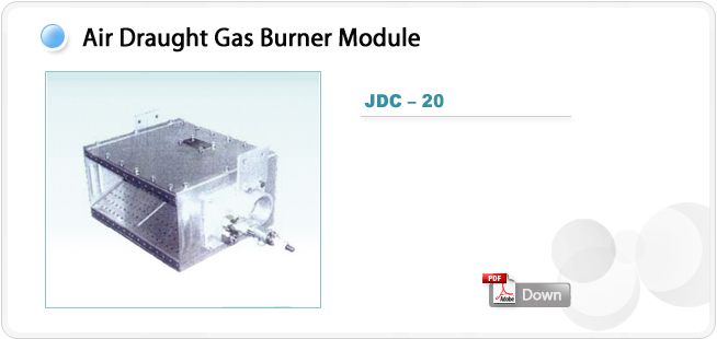
GENERAL INFORMATIONS
The “JDC…” gas burner represents a new concept of direct heating air for industrial process optimizing
mixing velocity of warm gases produced by combustion, with process air.
They are properly classified as “head mixing burner”.
For their suitable working, they need low pressure of air and gas.
“Linear” and “cross” models are available; these models, correctly assembled, may represent a never
ending variety of adaptable conformation to every conduct shape (size) and every application required.
The basis unit include housing burner with ignition probe, pilot burner and integrated ionization
electrode, or UV detection cell.
Three different construction modes are available depending on working process air temperature”
B – Low Working Temp. T max. (upstream burner) = 350℃
T max. (downstream burner) = 500℃
M – Average Working Temp. T max. (upstream burner) = 600℃
T max. (downstream burner) = 700℃
A – High Working Temp. T max. (upstream burner) = 700℃
T max. (downstream burner) = 800℃
Combustion air may be supplied directly from the process or from a blower (depending of installation
type). In case that air of combustion is supplyed by the process, the burner is called “OPEN-BACK”.
Process air must have a minimum oxigen tenor of 17% with a flow speed of 20m/s; the pressure drop in
this application if 2.5 mbar. If combustion air is supplyed by a blower, burner module will be equipped
with a connection flange; in this case low oxigen tenor won’t prevent burner to have a good combustion.
Anyway in order to have a good thermal distribution, it will be necessary to have process air speed
between 10m/s and 20m/s. In order to allow a good firing operation, a straigth duct section of about 1m,
before and after the burner, should be provided. Burner thermal capacity depends on linear dimensions
and may be easyly calculated with the help of the following table:
● Straight Module : 233Kw (200,000Kcal/hr)
Turndown rate depends on regulation type as follow:
● Gas/Air regulation (costant combustion ratio) - 10:1
● Gas regulation (costant air flow) – 10:1
Materials used in burner construction may vary depending on the kind of use it is designed for and are
generally made of refractory steel and/or Nickel-Crhome alloys.
FEATURES
+ Main module direct electrical ignition thanks to electrode:
or indirect thanks to a pilot incorporated in burner structure.
+ Flame detection with ionization electrode or UV cell.
+ Standard executions for Methane gas and LPG, other gaseous fuel on request.
APPLICATIONS
+ All types of application in which a large exchange surface between combustion gas and process air is
required, and it’s necessary a fast and uniform mixing.
+ Ceramic, Bricks, Refractory: Intermittent and continuous dryers.
+ Surfaces treatment: Painting kilns, enamelling kilns and dryers.
+ Printing and Packing: Air Heaters for Rotogravures, Flexographic and Coupling and adhesive coating Machines.
+ Food: Cereal, fodder and tobacco dryers, roasters.
+ Moreover for all those applications in which a gas burner at large regulation and automatic working is required.
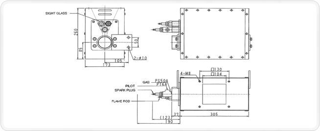
TECHNICAL DATA
MODEL |
JDC-20 |
| OUTPUT MAX. (refer to 152 mm) |
233 kW (200,000 kcal/h) |
| MAX.-MIN. RATIO |
10 : 1 |
| FUEL |
CH4/LPG |
| BURNER MATERIAL |
Ni-Cr Alloy |
| *FLAME LENGTH |
1,000 mm |
| GAS SUPPLY PRESSURE |
40 mbar |
| AIR SUPPLY PRESSURE |
10 mbar |
| MIN. COMBUSTION AIR EXCESS |
20 % |
| **LOAD LOSS |
2.5 mbar |
The mentioned performance data are described at their maximum power. Pressure showed are guidelines only.
Gas pressures are refer to Methane gas.
* Flame length has conditioned by process air speed (~10m/s) and by the combustion air in excess to 30%.
** The load loss onto burner depend to the process air speed. The load loss indicated are refered to a speed of 10m/s
Performance data and dimensions are guidelines only.
+The descriptions and specifications are subeject to change without notice.
|